
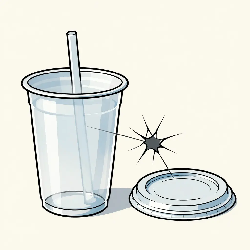
The Physical Failure Mechanism: Why PET Cups Crack When a Lid Snaps On
A cracked rim doesn’t appear out of nowhere. It is where a force conflict that starts the moment a lid meets the cup finally gives way. During a snap-on, the lid’s inner snap ring has to pass over the cup’s outer rim; because the two parts are designed to lock, the lid is deliberately smaller than the rim it captures. The size difference is the radial interference, and the cup deforms to absorb it. Knowing how that sequence plays out is the quickest way to separate a wall-thickness problem from a lid-geometry problem.
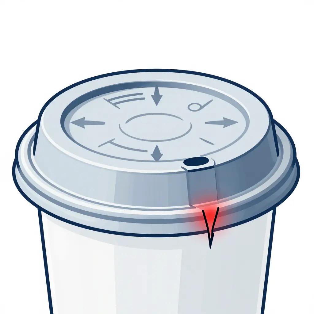
From Radial Interference to a Crack
- Radial interference loads the ring. The snap ring squeezes the rim inward. The rim is a closed circular section, so it resists that push with hoop stress, a circumferential tension running around it much like a stretched rubber band. By the time the lid finishes seating, the rim is already pre-loaded.
- Stress concentrates at the rim lip. The sealing edge and any sharp corner on the flange behave like geometric notches. Local tensile stress there can run several times the nominal hoop value, which is why the rim lip reaches its failure threshold first.
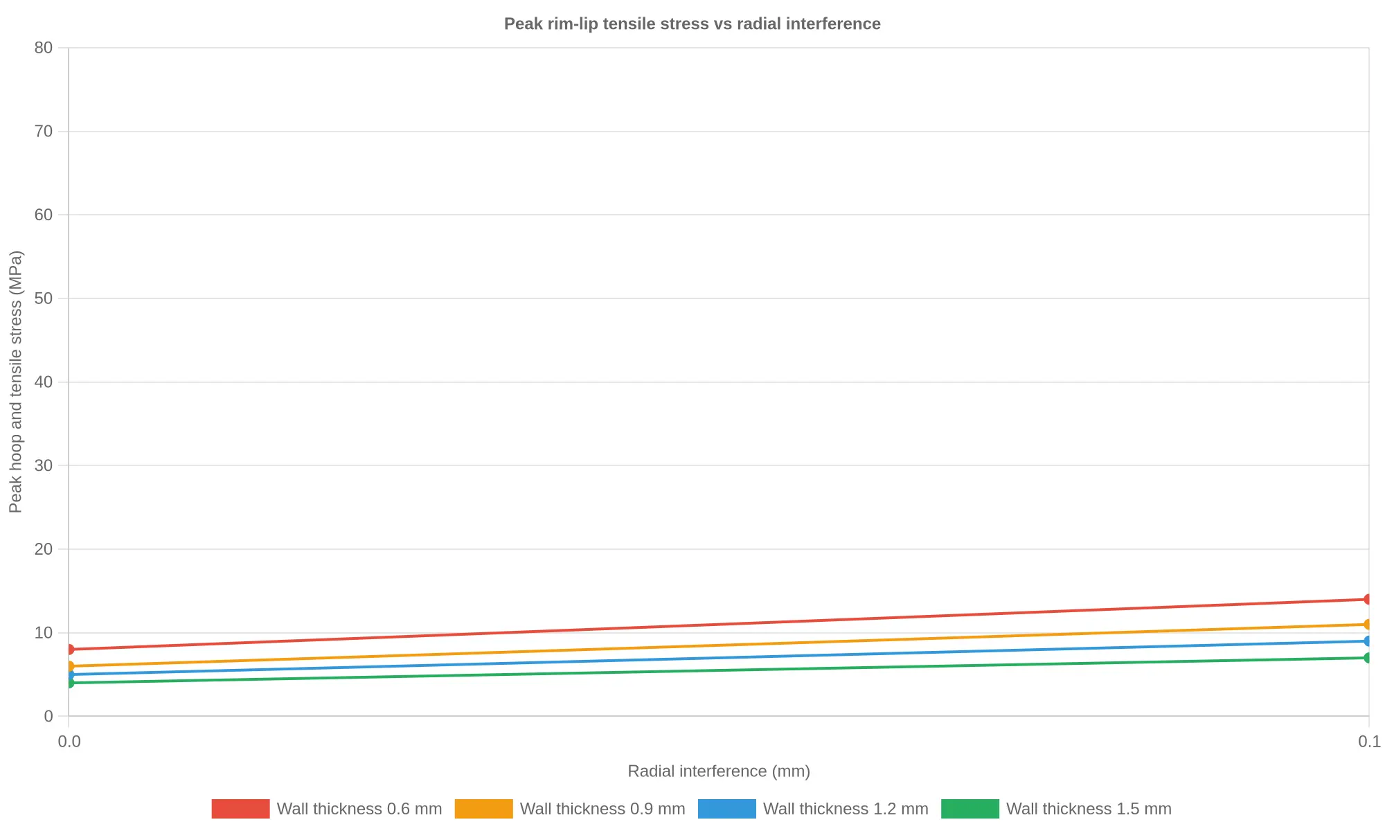
- Thin or crystallized PET has little fracture toughness. Drawn thin, or oriented by cold-drawing at a low temperature, the material gains stiffness and loses ductility. Almost no plastic yield zone remains to blunt a crack tip, so once local tensile stress passes the material’s toughness, the crack propagates rather than deforms. The chart below shows peak rim-lip stress climbing with radial interference, and how much sooner thin walls reach a critical level.
- Rapid, uneven downward force amplifies the peak. Slamming one side of the lid down first tilts the rim and puts the whole interference load on a single arc instead of spreading it around the circumference. That asymmetric spike turns a stress the rim could survive into an instant fracture.
Reading the Crack: Morphology as a Diagnostic
| Crack type | Appearance | What it signals |
|---|---|---|
| Clean vertical split | Straight, sharp-edged, runs parallel to the cup wall axis | Wall is thick enough to be brittle; a locally oversized lid snap ring or a hard, crystallized rim area is the culprit |
| Stress-whitening crack | White, cloudy halo around the crack path | Ductile draw occurred before failure – the wall is thin and cold-drawn, absorbing strain before it finally tore |
| Hairline crack at the sealing edge | Faint, short micro-crack only at the flange lip | Marginal interference or a tight corner radius; the crack is incubating and will propagate on the next few lid cycles |
A clean vertical split points to a stiff rim and an over-tight lid. A stress-whitening crack points to a wall that is too thin and a cold, low-toughness draw zone. A hairline crack at the sealing edge is the early warning that lid geometry and rim profile are only barely compatible. The decisive test is to measure rim outer diameter against lid inner diameter instead of trusting nominal sizes. For shops sourcing matched drinkware, it pays to confirm that lid and cup were engineered as a pair, which is why many buyers standardize on clear plastic cups with lids specified together to a single interference tolerance.
Specification Matrix: Rim Wall Thickness vs. Lid Inner Diameter and Cracking Risk
Table 1. Reference guide only, mapping nominal cup rim wall thickness (rim area) to recommended lid inner diameter and expected cracking risk; because PET lid-fit performance is governed by cumulative tolerance stack-up, all values must be validated on the actual production line before full-scale conversion.
| Cup Size (oz) | Rim Wall Thickness (mm) | Recommended Lid Inner Diameter (mm) | Interference Fit Range (mm) | Cracking Risk Level |
|---|---|---|---|---|
| 10 | 0.32 – 0.38 | 76.0 – 76.4 | 0.10 – 0.18 | Low |
| 12 | 0.40 – 0.46 | 89.0 – 89.4 | 0.15 – 0.28 | Low |
| 12 (heavy-wall) | 0.50 – 0.58 | 89.3 – 89.8 | 0.30 – 0.48 | Moderate |
| 16 | 0.48 – 0.55 | 90.0 – 90.5 | 0.20 – 0.40 | Moderate |
| 16 (heavy-wall) | 0.60 – 0.72 | 90.3 – 90.9 | 0.35 – 0.55 | High |
| 18 | 0.52 – 0.60 | 92.0 – 92.6 | 0.25 – 0.45 | Moderate |
| 18 (heavy-wall) | 0.68 – 0.82 | 92.6 – 93.3 | 0.45 – 0.65 | High |
How to read this table: The Interference Fit Range is the diametral compression applied to the cup rim when the lid snaps on, and it grows as rim wall thickness increases. Thin rims (0.32 – 0.46 mm) flex elastically, which keeps hoop stress below the PET yield point. Past roughly 0.60 mm, the same lid geometry drives far more hoop stress into a stiffer section, and the risk of stress-cracking at the rim climbs from Moderate to High unless the lid inner diameter is opened up to match. Pair these nominal figures with your measured wall-thickness distribution, then confirm snap force and leak integrity in a short pilot run before committing to a full order. Our team can help you cross-check against production-grade clear PET cup and lid specifications.
Wall Thickness Analysis: The Variable That Decides Whether a Rim Survives the Lid
When a clear PET cup fractures as a lid snaps down, the lid’s inner diameter usually gets the blame. In many field failures, the real cause sits a few millimeters from the sealing groove: wall thickness at the rim. Before you retool a lid, measure the cup.
How Rim Wall Thickness Governs Hoop Stress and Bending
A cup rim acts like a thin structural ring. When the lid presses inward and levers against the lip, the ring resists two loads:
- Hoop stress – the circumferential tension pulling the ring outward.
- Bending stress – the localized flex where the lid lip pivots on the rim edge.
Thicker walls resist both, but not equally. Hoop capacity scales roughly linearly with thickness; bending stiffness scales with the cube of thickness. A rim at 0.45 mm instead of 0.35 mm is not simply “30% stronger”. In bending it is more than twice as stiff. That is why rim rigidity, more than the lid design on its own, decides whether the sealing edge flexes and survives or cracks under the snap force.
How Extrusion and Thermoforming Thin Spots Become Crack Initiation Points
Extrusion and thermoforming never produce perfectly uniform walls. Draw-down over a deep plug, uneven sheet heating, and variable vacuum timing all pull material away from high-draw zones, leaving thin spots at the rim. A thin section concentrates stress the way a machined notch does: the surrounding rigid material forces it to absorb the full bending moment, so the crack usually starts where the wall is thinnest and then propagates radially. Two cups from the same mold can fail differently because their minimum rim walls differ by a few hundredths of a millimeter.
Cooling Rate and Residual Orientation in the Rim
Cooling speed sets the rim’s mechanical character. Fast, uneven cooling freezes in residual molecular orientation and internal stress, leaving a rim that is stiff but brittle and fractures on the first lid application. Slow, controlled cooling relaxes that orientation and leaves a more ductile rim that flexes instead of shattering. As a diagnostic, a rim that cracks cleanly and loudly on the first snap but behaves once re-warmed points to cooling or orientation, not dimensions.
Nominal Wall Thickness vs. Minimum Rim Wall Thickness
This distinction decides most supplier disputes. Nominal wall thickness is the design target or average, the number on the drawing. Minimum rim wall thickness is the thinnest reading anywhere on the sealing circumference. Cracking is governed almost entirely by the minimum, because a structure fails at its weakest point. A cup “specified at 0.5 mm” that hides a 0.31 mm thin spot cracks like a 0.31 mm cup, however healthy the nominal figure looks on paper.
Practical Thresholds
| Minimum rim wall thickness | Cracking risk | Diagnostic note |
|---|---|---|
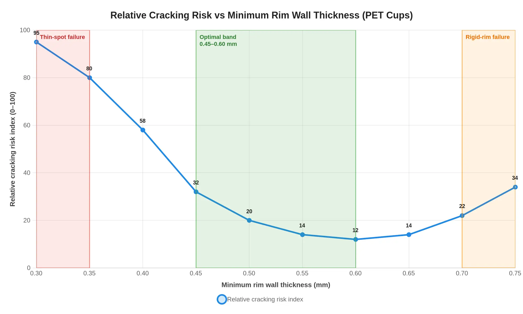
| Below 0.35 mm | Sharp rise – critical | Crack initiation near-certain at snap |
| 0.35-0.45 mm | High to moderate | Highly sensitive to lid tolerance |
| 0.45-0.60 mm | Low – optimal band | Best balance of flex and strength |
| Above 0.70 mm | Rising again | Rigid rim resists lid flex |
Below roughly 0.35 mm, cracking risk rises sharply; below 0.30 mm, failure on the first lid application becomes the norm rather than the exception.
When a Rigid Rim Cracks, Too
Excess thickness cracks cups too. An over-thick, rigid rim refuses to flex as the lid’s retention bead rolls over it, so instead of yielding elastically the stress transfers to the adjacent wall and splits it. The radial cracks look the same as those from a thin spot; the cause is opposite. On a standard 16 oz clear PET cup, rim walls above roughly 0.70 mm paired with a tight lid inner diameter often trigger this rigid-rim failure. Excess rim rigidity also makes the lid hard to seat, which tempts the operator to force it and makes the fracture worse.
Measurable Parameters Inspectors Should Verify
- Minimum rim wall thickness at 8-12 points around the circumference.
- Wall thickness variation (max minus min) across the rim – flag anything exceeding 0.05 mm.
- Delta between nominal and measured wall thickness.
- Rim outer diameter, inner diameter, and ovality.
- Cooling-related haze or stress whitening at the rim.
- Lid inner diameter versus rim outer diameter interference (snap fit).
- Crack location pattern after a controlled snap test – rim edge, thin spot, or adjacent wall.
Measure the minimum, not the average. The thinnest point on the rim is where every crack begins.
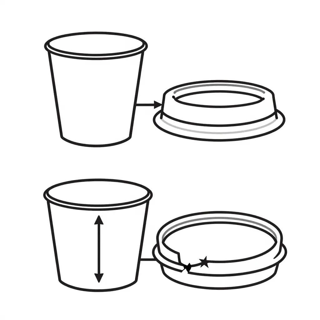
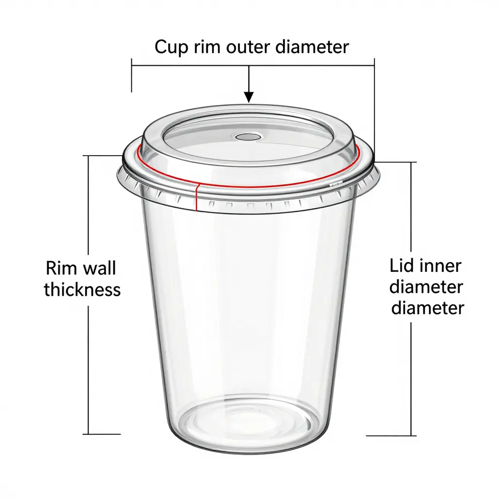
Two-state schematic of the lid-to-rim interface: before engagement (top) and during engagement (bottom), where radial interference generates hoop stress that concentrates at the rim lip.
Lid Inner Diameter: The Hidden Variable Behind Rim Cracking
When a clear PET cup cracks as the lid snaps into place, the instinct is to blame wall thickness. More often the real cause is at the interface: the lid inner diameter and how it engages the rim. The rim is only as strong as the stress the lid puts on it, and that stress is set almost entirely by the difference between the lid’s inner snap diameter and the rim’s outer diameter.
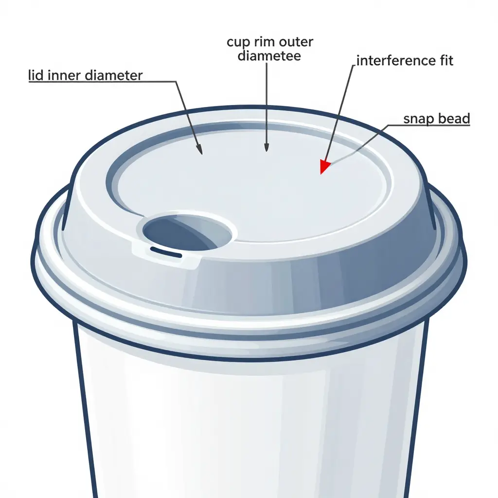
Interference Fit: Where the Load Begins
A snap-on lid holds by interference fit: the lid’s inner snap bead is molded slightly smaller than the rim it grips. As the lid seats, the bead is forced over the rim and compresses, generating a radial hoop force that presses inward while the rim pushes back against the bead. The strain is designed and balanced. Problems start when interference drifts off nominal in either direction.
Lids Too Small: Excessive Outward Stress on the Rim
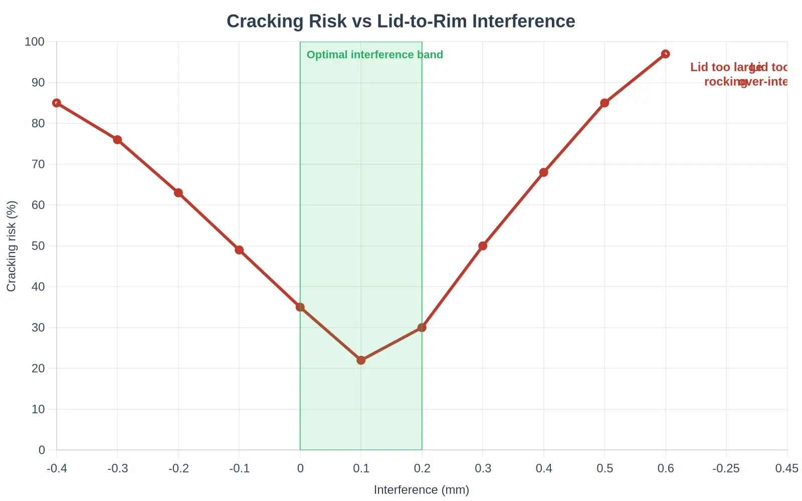
An undersized lid inner diameter pushes interference past the design window. The bead has to stretch further to seat, and that stored elastic energy becomes a larger outward radial load concentrated at the rim’s top edge, the thinnest and least supported region. PET is notch-sensitive, so stress risers on the rim – gate marks, mold seams, micro-scratches – turn into crack initiators. The failure shows up as a vertical split at the rim, often minutes to hours after capping as residual stress relaxes.
Lids Too Large: Rocking Concentrates Flexing at One Segment
An oversized lid inner diameter may still “click,” but with little or negative interference. The lid seats loosely and rocks under lateral load from stacking, carrying, or straw insertion. Rocking turns what should be a uniform hoop load into a cyclic bending moment on a single rim segment. Repeated flexing at that segment fatigues the PET and starts a hairline crack that propagates. This shows up as an off-center, single-sided crack rather than an even split.
Dimensional Tolerance of Molded Lids
Molded lids never come out at exactly the nominal inner diameter. Each carries a tolerance band built from tooling dimensions, mold wear, process drift, and cooling variation. If that band is too wide, some lids in a batch behave as “small” and others as “large,” and the same line shows mixed failure modes. Fit stabilizes when you tighten the tolerance on the critical snap diameter rather than on the lid as a whole.
Shrinkage Variation Between Resin Lots
Even with a perfect tool, a change of resin lot shifts dimensions. Molecular weight distribution, regrind ratio, moisture content, and even pigment masterbatch all change the shrink rate. Because the snap diameter is a small feature, a 0.2-0.3% shrink shift can move the critical dimension by tenths of a millimeter – enough to flip a lid from loose to over-interfering. Lot-to-lot consistency takes incoming inspection and, where possible, a single qualified resin source.
Lid Concentricity and Roundness
Lid concentricity – how well the inner snap circle shares a center with the lid’s outer geometry – decides whether the seating load is evenly distributed. An eccentric snap bead engages on one side first and carries most of the load, mimicking a “too small” lid on one side and a “too large” lid on the other. Poor roundness in the snap ring does the same thing, creating high- and low-interference zones around one circumference. Either defect breaks the assumption of uniform hoop stress.
Recommended Practice: Match to Measured Rim, Not Nominal Size
The most effective fix is to stop matching lids to a nominal cup size (“16 oz”) and start matching them to the measured rim outer diameter.
- Measure rim outer diameter at multiple points across multiple cups per lot; use the min/max range, not the average.
- Specify lid inner snap diameter to a target interference band based on measured rim OD – typically a narrow range around the rim’s maximum.
- Control the two features that dominate fit: snap diameter and concentricity/roundness.
- Share measured rim data with your lid source. For anything beyond stock closures, custom lid tooling should be built around your measured rim tolerance rather than a catalog number.
Failure Signatures Tied to Lid Dimensions
| Failure signature | Likely lid dimension cause |
|---|---|
| Even vertical split at rim, all cups | Lid inner diameter too small (over-interference) |
| Single-sided / off-center crack | Poor lid concentricity or roundness |
| Cracks only when stacked or carried | Lid too large, rocking under lateral load |
| Mixed splits and loose fits in one batch | Excess dimensional tolerance |
| Sudden onset after resin change | Shrinkage variation between resin lots |
| Cracks worst opposite a mold seam | Eccentric snap bead plus rim stress riser |
Match the lid inner diameter to a measured rim, control concentricity, roundness, and lot-to-lot shrinkage, and lid fit becomes a specified, repeatable process instead of a guess.
Crack Rejection Rate vs. Rim Wall Thickness
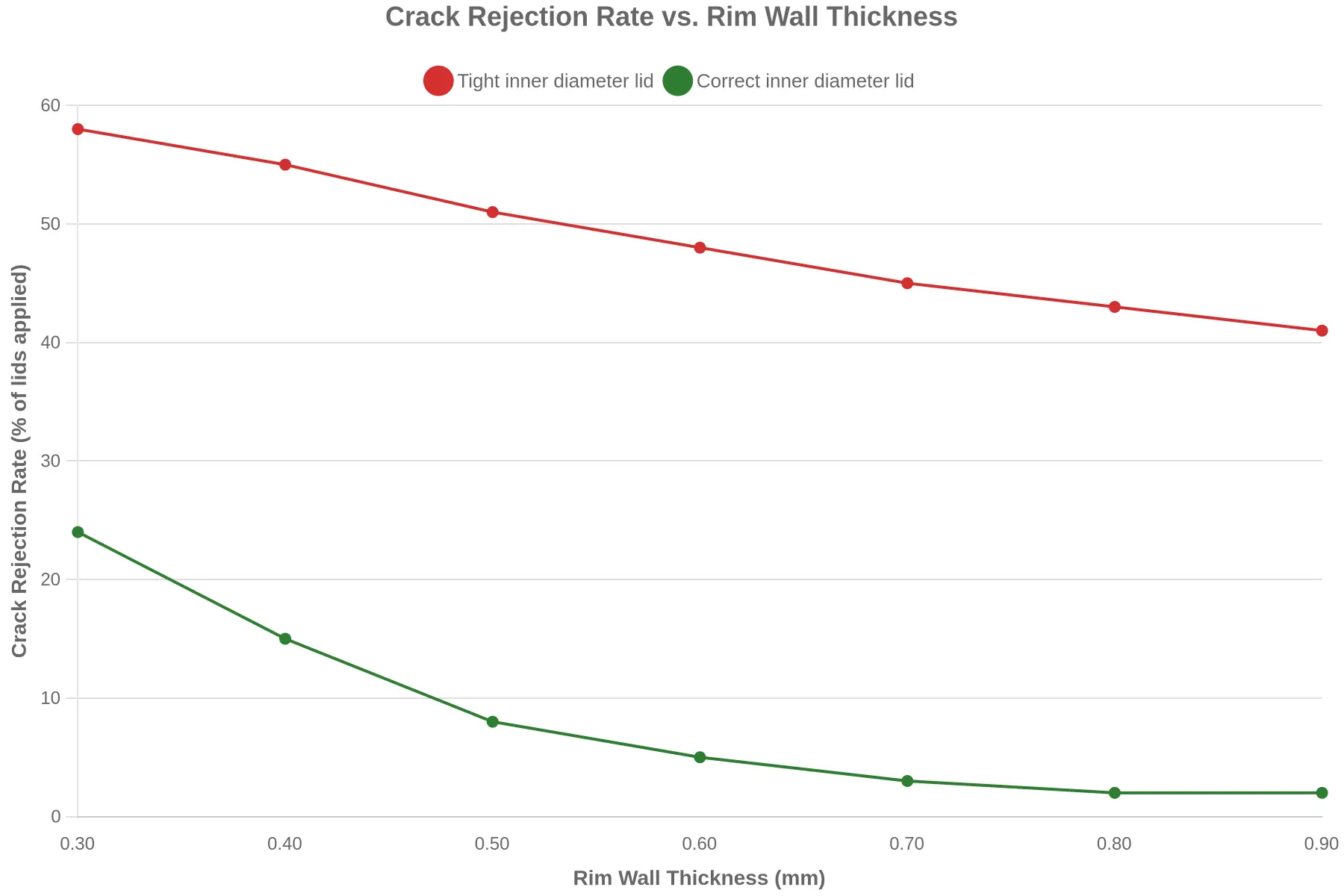
Wall thickness alone does not tell the whole story. The chart below plots how often lids actually crack when snapped onto clear PET cups across a realistic range of rim wall thickness, comparing a lid with an undersized (tight) inner diameter against one with a correctly matched inner diameter.
How to read this data
Two patterns stand out, and they point to the same troubleshooting rule:
- The green line (correct inner diameter) falls steeply as the rim walls thicken. From a thin 0.30 mm rim to a 0.70-0.90 mm rim, the crack rejection rate drops from roughly 24% to 2%. A thicker rim gives the lid more material to bite into and spreads the hoop stress better, so cracks become rare.
- The red line (tight inner diameter) stays high. Even at a 0.90 mm wall, the crack rejection rate is still around 41%. The mismatch forces the lid to stretch past its design tolerance on every snap, so the stress concentration never goes away, however much material you add.
Why this matters for your operation
Thickness and diameter are interdependent, not interchangeable. Adding wall thickness fixes cracking only when the lid’s inner diameter is specified to match it. If a supplier swaps in a tighter lid to solve a separate leak or retention complaint, extra thickness elsewhere will not compensate: you keep paying for cracked lids and wasted product. For buyers and packaging engineers, the chart is a practical argument for verifying lid inner diameter against the cup’s actual rim dimension before signing off on a run.
If you are sourcing matched cup-and-lid sets, work with a partner who tunes both components together. Explore OEM lid options designed for your exact cup dimensions to catch snap-fit failures at the source.
Tolerance Stack-Up: Why Wall Thickness and Lid Diameter Can’t Be Specified in Isolation
Cracking complaints about clear PET cups tend to start the same way: the drawing passes, the pilot samples pass, then the line starts splitting rims at the snap. The cause is rarely one bad dimension. It is a tolerance stack-up – independent variations accumulating until they collide at the sealing interface the moment a lid is pressed on.
A cup and lid never meet at their nominal dimensions. They meet at whatever the process produced on that shift. Three contributors govern the fit:
| Contributor | Dimension | Direction that increases interference | Typical tolerance |
|---|---|---|---|
| Cup rim outer diameter | OD_rim | Larger rim | +/- 0.10 mm |
| Rim wall thickness | t_rim | Thicker wall (raises hoop stress) | +/- 0.05 mm |
| Lid inner diameter | ID_lid | Smaller lid bore | +/- 0.08 mm |
The actual diametral interference is driven by the rim-to-lid relationship and amplified by wall stiffness. A wall that is too thin flexes and leaks; a wall that is too thick concentrates the snap force and triggers PET cup cracking. The worst-case interference in the tightening direction is the sum of the tolerances added to the nominal value:
Iworst = Inominal + (TrimOD + Twall + T_lidID)
For a statistical view, stack them in root-sum-square instead: Irss = Inominal + sqrt(TrimOD^2 + Twall^2 + T_lidID^2). The worst-case method guards against the rare extreme; the RSS method describes the bulk of production. Use both.
The Control Window (Interference Band)
Instead of chasing a single “correct” interference, define an interference band: a control window whose lower limit prevents leaks and whose upper limit stays below the cracking threshold. Any point inside the window seals without over-stressing the rim; any stack-up that drives interference above the band snaps the material.
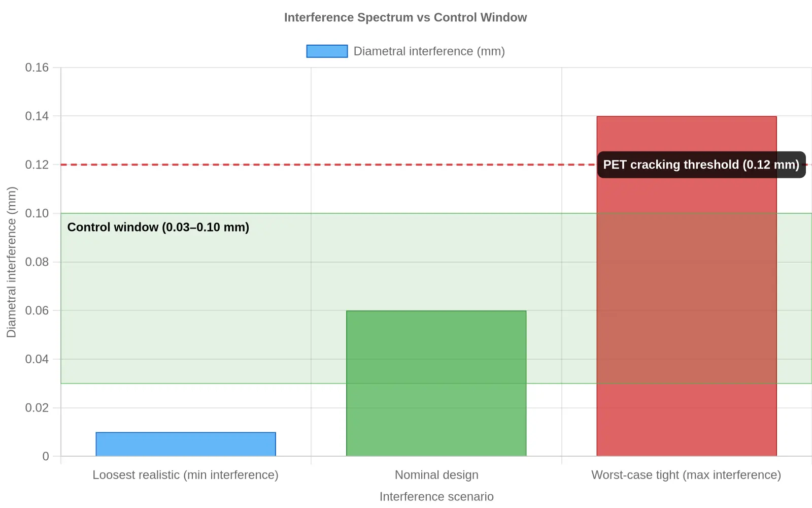
A design can sit exactly on nominal and still fail in production, because the extremes of three independent tolerances can land on the same part. Nominal is a target; the stack-up is the reality.
Steps to Define and Validate a Control Window
- Establish the functional limits: the minimum interference that seals and the maximum the rim tolerates before crazing.
- Measure true process capability for rim OD, rim wall thickness, and lid ID on real production samples – never trust drawing nominal.
- Calculate worst-case and RSS interference using the formulas above.
- Set the control window with a safety margin below the cracking threshold.
- Rebalance tolerances by tightening the dominant contributor rather than every dimension.
- Validate with snap-force testing and continuous Cpk monitoring on the line.
When you are sourcing matched cup-and-lid sets, confirm the supplier stocks both parts from one tolerance scheme. A control window holds only if the cup and lid are engineered as one system.
Troubleshooting Checklist: Clear PET Cup Cracking When Lids Snap On
Work through these in order, from quick measurements to deeper process and tooling changes. Each step says what to do and why it matters for lid fit.
-
Measure the actual rim wall thickness with the right gauge. Use a dedicated rim or bead micrometer, not a flat caliper, to read true wall thickness at the sealing lip where stress concentrates. A wall below spec is the most common cause of cracking when lids seat, so log readings around the full circumference instead of trusting one spot.
-
Verify the lid inner diameter with pin gauges. Push a calibrated pin gauge or use a bore gauge to check the lid’s inner diameter against the drawing. A lid on the tight side of tolerance forces the rim outward on every closure and starts a stress crack, a mismatch you can catch in seconds before blaming the resin.
-
Check lid-to-cup concentricity. A lid that is off-center concentrates closing force on one side. Rotate it on the cup and watch for uneven engagement; out-of-round parts point to tooling wear or uneven thermoforming, either of which disrupts fit no matter what the nominal dimensions say. For guidance on handling different cup sizes, see these clear plastic cups with a handle.
-
Control application force and angle. Train operators and calibrate lidding equipment so lids are pressed straight down with consistent force. Pushing at an angle or slamming the lid shears the rim, so document a target force window and recheck it whenever you switch product sizes, including formats like wholesale 9-ounce clear plastic cups.
-
Adjust thermoforming cooling or extrusion parameters. Uneven cooling leaves residual stress and thin spots, so balance mold temperature, dwell time, and cooling zones. On extruded sheet, tune draw and temperature profiles to keep wall distribution uniform.
-
Review resin grade and intrinsic viscosity (IV). A resin with the wrong IV or too much regrind turns brittle and cracks under snap-on load. Confirm the grade suits your rim geometry and keep regrind ratios under control.
-
Audit incoming dimensional inspection. Sample rim diameter, wall thickness, and squareness for every incoming lot. Catching out-of-tolerance parts at the dock keeps a cracked-cup problem off the packaging line.
-
Request matched tooling from the supplier. If measurements stay in spec and cracking continues, ask for a matched cup-and-lid tool set built to one controlled tolerance stack. It is the deepest fix, but it removes the mismatch at the root.
Root Cause Distribution in Clear PET Cup Cracking Complaints
When lids snap onto clear PET cups and the rim spider-cracks, the cause is rarely one factor. The doughnut chart below shows how field complaints typically distribute across the six most common root causes. Treat it as a triage map: start your investigation with the largest segments.

Reading the Segments
| Root Cause Segment | Share | What It Signals |
|---|---|---|
| Under-thickness rim wall | 28% | The rim wall gauge is below spec, so it flexes and fractures under lid snap load |
| Oversized lid inner diameter | 22% | Lid bore runs too large, forcing the rim to stretch outward and split |
| Undersized lid inner diameter | 14% | Lid bore runs too tight, generating hoop stress that cracks the rim on seating |
| Incorrect lid application force | 14% | Manual or automated press force is too high or applied at an angle |
| Cold/aged PET material | 12% | Resin stored cold or aged loses toughness and cracks more easily |
| Tooling wear and tolerance drift | 10% | Worn molds or drifting tolerances produce inconsistent rims and lids |
The chart is for prioritization, not blame. The two largest segments – under-thickness rim wall and oversized lid inner diameter – account for roughly half of all complaints, so verifying the rim gauge and lid bore is the most efficient place to start. Rule those out, then work down the list to application force, material condition, and tooling drift.
How to Act on This Distribution
- Measure first, guess later. Pull a sample of cracked cups and their mating lids and record rim wall thickness and lid inner diameter before changing anything.
- Check the material bin. Confirm PET resin storage temperature and age; cold or aged material shifts the whole failure curve.
- Audit the line. Verify lid application force settings and tooling maintenance logs against the tolerances that matter most.
How cup geometry and lid fit interact decides whether rims crack before they reach your customers. See this guide to clear plastic cups with lids for the specification details buyers should confirm with any supplier.
Conclusion and Supplier Guidance
Cracking when lids snap onto clear PET cups is not random. It is the predictable, measurable result of how two interfaces interact. Specify wall thickness and lid inner diameter as an engineered interference system and rim cracking becomes preventable; treat them as independent dimensions and failure is inevitable. The distinction matters for anyone running high-volume beverage service.
Three practices turn it into a controlled process:
- Measure actual, not nominal, dimensions. Drawings and data sheets describe intent; production parts describe reality. A wall tolerance that reads “0.3 mm” on paper may arrive at 0.26 mm, which changes interference and stress at the rim.
- Define a control window. Establish an upper and lower limit for rim thickness and lid inner diameter, then confirm incoming lots against it. A defined window lets you detect drift before it reaches the sealing line.
- Standardize matched cup-and-lid sets. Route cups and lids through one validated pairing rather than mixing suppliers and molds. Matched sets remove the guesswork that produces hairline fractures under snap force.
For teams evaluating tighter specifications, a dedicated plastic disposable cup manufacturer in China can supply documented dimensional data across product families.
GreenDispopack manufactures and supplies disposable tableware and packaging, with a focus on safety, durability, and eco-friendly practices. Our technical team handles tolerance reviews and matched tooling design. Procurement managers and engineers can request detailed dimensional specifications, sample matched cup-and-lid sets, or tailored tooling for formats such as 18 oz clear plastic cups with lids. Specify the interference system, control the window, and the cracking stops.